Shader Graph can be used to create some cool effects. Dissolve is a very common effect used in many games and also looks cool. In this tutorial, we will see how to use Shader Graph in Unity to create a simple dissolve effect.
Shader Graph package need to be installed in your project. The menu items may slightly differ based on the Render Pipeline. If you are totally new to shader graph then check out our getting started tutorial for shader graphs in Unity.

Creating New Shader
After you have installed the Shader Graph package and set the required Render Pipeline then go to the project window and right click. Select Create>Shader Graph>Built-in (name of Render Pipeline)>lit. Let’s name the Shader Graph as Dissolve.
Select the Dissolve shader and right click>Create>Material. Let’s name it Dissolve_effect. Add a simple cube to your scene and add the material to your cube. This will allow us to preview the changes that we do in the Shader Graph editor.

Editing the Unity Shader Graph for Dissolve effect
Double click on the Dissolve Shader and it should open up the Shader Graph editor. The default layout consists of a Graph inspector, Blackboard and a Main preview window. The center part is where you create the shader logic. It has a Vertex and Fragment block. These blocks are the basic properties of the shader.
The blocks inside your Shader Graph will differ based on whether you have selected a lit or unlit shader.
You can add a Shader Node and a Block node. To add a Block node just select the Block>Right Click and select Add Block node. To add a shader node, you can just right click on the workspace and select add node.

We need two major nodes in our Fragment block to create the dissolve effect. The first one is Alpha and the other one is Alpha clip threshold. Select the Fragment block>Right Click>Add Block node and select Alpha from the list. Do the same thing for Alpha clip threshold.
You might see that both Alpha and Alpha clip threshold are greyed out. To enable them you need to go to the Graph Inspector window> Graph settings tab and check Alpha Clipping.
Adding Noise to Alpha Channel
We will be changing the Alpha clip threshold to make the material dissolve. That means we need to provide the shader with a variable alpha channel. The best node that we have that can give a varied alpha value is the Simple noise node.
Right click on the workspace > Create Node and select Simple Noise.
Connect the output of the Simple Noise block to the Alpha node. Now vary the value of alpha clip threshold between 0 and 1 and you should see the dissolve effect in the preview.
You have created a dissolve effect. You need a way to change the Alpha Clip threshold from outside so that you can change it during runtime.
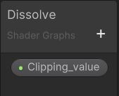
Let’s create a property of type float by clicking on the +sign inside the blackboard and name it as Clipping_value.
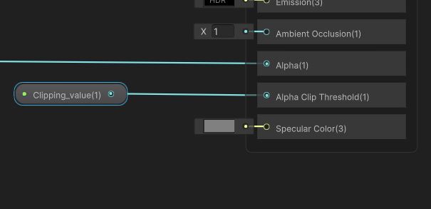
You can drag and drop this inside the workspace and connect it to the Alpha Clip Threshold input of the Fragment block.
Select the Clipping_value parameter and go to the Graph Inspector. Under the Node settings tab, set the mode as slider. Save the asset and let’s preview it in our scene view.
If you have not already applied the material to an object in the scene, drag and drop the material to the sample cube that we added in our scene. Select the material in the project window and you should see a slider for Clipping_value under the Surface Inputs. Adjust the slider and see your cube dissolve away.
Adding enhancements
Adding texture option
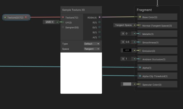
The shader does not have the option to add a texture to it. So, let’s add it. Right click and add a texture 2D asset node. Right click on the texture 2D asset and go to Convert To>Property. This will expose the property outside so that you can add the texture directly to your material.
You need to connect the texture 2D to base color node in the fragment block. You cannot connect it directly due to type mismatch. So, you need to use a Sample texture 2D node to extract the color information. This node will take in a 2D texture and give the color information as output.
Use the Sample texture 2D node to add the texture to the Base color node.
Adding a glow effect to the Edges
We will use the Step node and offset it a little to get the glow effect. The output of the step node will go to the Emission node of the Fragment block. The step node takes in two inputs. Connect the Simple Noise to the Edge input. Now let’s add a small offset to the Clipping_value and connect it to the IN input of the Step node.
If you need color for your edges then add a color node and multiply the output of the color node and the step node and connect it to the Emission node.

You can adjust the offset in the Add node and the size of the Simple noise to get the effect you need. Save the shader and have fun applying it on different objects. Here is how my shader looks.